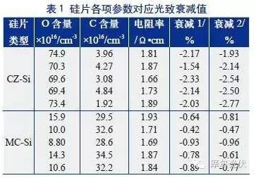
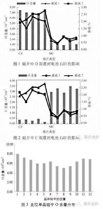
The study focused on the differences in the attenuation of Czochralski silicon cells and ingot polycrystalline silicon cells, as well as the causes of the differences. The results show that the formation of this difference is mainly influenced by the BO complex, carbon content, segregation coefficient and metal ions. introduction The large-scale promotion of solar cells and power generation technology has exerted a powerful impact on traditional fossil fuel power generation technologies. Today, with increasingly depleted energy sources and increasingly intensified environmental pollution, research has received much attention. Solar cells are mainly divided into silicon material batteries, semiconductor compound batteries, organic compound batteries, and perovskite batteries that have been actively researched in recent years, depending on the materials used. Among them, the crystal silicon battery in the silicon material battery is divided into two kinds of monocrystalline silicon and polysilicon battery, occupying about 90% of the market share [1]. As we all know, the single-crystal silicon cell photo-induced attenuation (LID) has always been a major problem that plagued the industry, especially in recent years, the newly developed and industrialized passivated emitter and local back contact (PERC) batteries, the LID value is even higher 3% to 5%; however, the same LID for p-type polysilicon cells is always lower. In the same boron-doped battery, different crystal growth methods ultimately result in different LID values. This article focuses on the influencing factors of LID and the effect of different crystal growth modes on LID values. 1, LID influencing factors The factors that affect LID are: 1) Boron Oxygen (BO) complex. The BO complex is one of the main factors affecting the LID. The LID value is proportional to the B concentration and is proportional to the square of the O concentration [2]. 2) Crystal internal carbon (C) content. High concentrations of C have inhibitory effects on the BO complex [3]. 3) Segregation coefficient. The segregation coefficient of oxygen in silicon is 1.25, so for Czochralski silicon, the O content of the head is relatively high and the tail is relatively low; and for the cast polysilicon, the bottom is solidified first, then the O concentration The highest; after the top of the solidification, the lowest concentration of O. 4) Decomposition of ferroboron (Fe-B) pairs - compound model. The Fe-B pair decomposes into Fe and B, and the high-energy Fe recombination center causes the silicon wafer to be contaminated by Fe, thereby causing deterioration of the battery performance. 2, experimental design 2.1 Test equipment The silicon C/O content, minority carrier lifetime, and wafer thickness parameters were measured using Nicolet 8700 Fourier infrared (FT-IR) spectrometer, German Semilab WT-1000 lifetime tester, and Shanghai Xingna MS203 wafer multi-parameter detector. The battery light treatment adopts the HS1610C hot spot endurance test device of Shanghai Solar Engineering Technology Research Center; the battery HALM measurement system before and after light measurement adopts the German HALM high-precision IV measurement system; and the FL-01 integrated machine of Zhongdao Optoelectronics Equipment Co., Ltd. is used for silicon wafers. Electroluminescence (EL) measurements of photoluminescence (PL) and batteries. 2.2 Test samples and treatment Collect polysilicon (MC-Si) and straight-pull single crystal silicon (CZ-Si) with the same resistivity (1~3Ω), test each raw silicon parameter and record accordingly; then pass the sample through the same battery. After the processing technology is processed, 10 cells are selected respectively. The hot spot durability test chamber was used for light treatment. The light intensity was 1000 W/m2 and the time was 5 hours. The same system was used to measure the battery performance parameters after illumination, and the attenuation ratio in the light process was calculated. 3, results and analysis The photo-induced attenuation values ​​for the various parameters of the silicon wafer are shown in Table 1, where attenuation 1 and attenuation 2 represent two tests of battery attenuation under the same conditions. From Table 1, it can be seen that the difference in MC-Si and CZ-Si attenuation of the same resistivity is mainly due to the change of O concentration and C concentration. Since the ceramic lanthanum is used in the MC-Si ingot casting process, its main chemical components are SiO2 (99%), Al2O3 (0.5%), GaO (0.5%), and Si3N4 coatings; while quartz is used in the CZ-Si pull process. Glass crucibles, the main chemical composition is a single high-purity SiO2 (100%), and the use of high-purity SiO2 as a coating material [4]. The ceramic cerium itself has a lower SiO2 content than the quartz glass cerium, and the Si content in the Si3N4 coating is higher. The pure SiO2 coating is lower, resulting in significantly lower polysilicon O content than monocrystalline silicon; in addition, the BO composite affects LID. One of the main factors is that the LID value is proportional to the B concentration and proportional to the square of the O concentration [2]; therefore, the low polysilicon O content is the main reason for the low attenuation of the polysilicon cell (as shown in Figure 1). The second is the carbon content, the segregation coefficient of carbon, and the difference in the thermal field distribution during the pulling and the ingot casting. The C content in MC-Si is significantly higher than that in CZ-Si, while the high concentration of C has the inhibitory effect on the BO complex. Role [3]. This is one of the reasons that causes the polysilicon cell to attenuate lower than that of the monocrystalline silicon cell. In addition, the factor that affects LID is the segregation coefficient. The segregation coefficient of O in silicon is 1.25. For CZ-Si, the head is solidified during the pulling process, so the content of O at the head is the highest; along with the melt The concentration of dissolved O that is contributing to yttrium increases again, and the concentration of O in the crystal increases again later in the process due to the effect of convection on the melt; the O concentration in the entire crystal shows a continuously changing curve, called the axial O-curve [5 ]. For MC-Si, the bottom is solidified first and the O concentration is the highest; at the top, the O concentration is the lowest. MC-Si has more grain boundaries and defects than CZ-Si. We investigated the issue of whether the defects will cause LID differences. The results show that defects have little effect on LID. This is consistent with the results of Wang Peng et al. [6] on the effect of defect on LID in MC-Si. 4 Conclusion Based on the above analysis, the following factors are responsible for the difference in photo-induced attenuation of MC-Si and CZ-Si: 1) Boron oxygen (BO) complex. Different tooling devices result in differences in O content in MC-Si and CZ-Si. The low polysilicon O content is the main reason for the low attenuation of polysilicon cells. 2) Crystal internal C content. The segregation coefficient of carbon and the different thermal field distribution cause the content of C in MC-Si to be higher than that of CZ-Si, and the high content of polysilicon C is one of the reasons for the low polysilicon cell. 3) Segregation coefficient. For CZ-Si, the O concentration in the entire crystal shows a continuously changing axial O curve. 4) The defect has little effect on LID. references [1] Xiao Huancheng. The solar cell market in the next five years belongs to monocrystalline silicon [EB/OL]. http://, 2014-11-19. [2] Schmidt J, Bothe K. Structure and transformation of metastable boron- and oxygen-related defect center in crystalline silicon[J]. Physical Review B, 2004, 69(2): 024107. [3] Macdonald DH, Geerligs LJ, Azzizi A. Iron detection incrystalline silicon by carrier lifetime measurements for arbitrary injection and doping [J]. Journal of Applied Physics, 2004, 95(3):1021 - 1028. [4] Chen Shengxian, Wang Xichong. Polysilicon ingot quartz ceramic crucible and coating [A]. Proceedings of the Tenth China Solar Photovoltaic Conference [C], Changzhou, 2008. [5] Ben D, Mohamed H, Ajeet R. Light induced degradation in Cochralski silicon during illuminated high temperatureprocessing[A]. Conference Record of the 29th IEEE[C], NewOrleans, Louisiana, 2002, 348 - 351. [6] Damiani B M. Investigation of light induced degradation inpromising photovoltaic grade silicon and development of porous silicon anti-reflection coatings for silicon solar cells[D]. Georgia: Georgia Institute of Technology, 2004.
Carbon Steel Press fittings pipeline system is widely used in hot water supply, fire protection.
Compared with traditional pipeline system, it`s not only more economical, safer and healthier,
but also easier and faster for installation with longer service life.
1. Carbon Steel Press Fittings range:
Coupling -- Equal coupling, Reducing coupling, Slip coupling, coupling with male/ female threads;
Elbow -- Equal elbow, Elbow 90°, Elbow 45°, Reducing elbow, Elbow with plain end, Elbow with wall plate, and Elbow with male/ female threads;
Tee -- Equal tee, Reducing tee, Tee with wall plate, and Tee with male/ female threads;
Others-- Pipe cap, Pipe Bridge and Flange connector.
2. Material: Galvanized carbon steel, 1.0034C-Stahl,Kohlenstoffstahl, ACCIAIO AL CARBONIO.
3. Size: 3/8``-4``inch or as request, pipe wall thickness: 1.0--2.0mm
Sizes range:
DVGW W534:1995: 15, 18, 22, 28, 35, 42, 54, 76.1, 88.9, 108mm.
JIS G 3448-1980: 15.88, 22.22, 28.58, 34.00, 42.7, 48.6, 76.1, 88.9, 108mm.
4. Standard:
Press fitting standard: (DIN) DVGW W534-1995; (JIS) JWWA G116:2001; GB/T 19228.1-2003
Pipe standard: DIN10312:2003; GB/T 19228.2-2003
O-ring sealing standard: CEN EN 681-1:2006; GBT 19228.3-2003
5. O-Ring Seal: "Chlorinated butyl rubber" (CIIR), EPDM, HNBR, NBR and FKM, etc.
EPDM (black): max working pressure 16bar, working temperature from -20℃ to 120℃, Suit medium: cold and hot water, compressed Air etc.
6. Galvanization: all carbon steel pipe fittings are plated with rust-resistant zinc.
7. Anneal: all stainless steel pipe fittings are annealed in inert gases before packing.
Installation and Connection Order
Equipments And Quality Control
Orderly Workshop
Efficient Anneal Equipment
Pressure Testing
Tensile Testing
Carbon Steel M Profile Press Fittings(DVGW) Carbon Steel M Profile Press Fittings,Carbon Steel Press Fittings,Steel Press Elbow Extension Fitting,M Profile Carbon Tee WENZHOU KASIN VALVE PIPE FITTING CO., LTD. , https://www.kasinvalvefitting.com