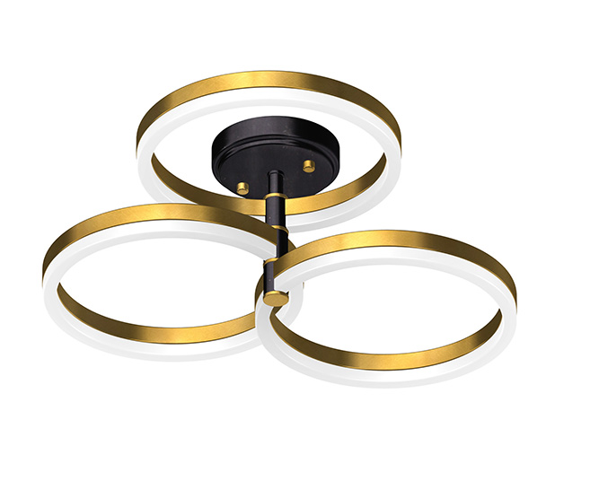
A Semi-Flush Mount is a type of Lighting Fixture that is installed on the
ceiling and hangs down slightly, but not as far as a Pendant Light. It
is a popular choice for rooms with low ceilings, as it provides ample
Lighting Product without taking up too much vertical space. Semi-Flush Mount Lighting come
in a variety of styles and designs, from modern and sleek to more
traditional and ornate. Semi-Flush Light are typically easy to install and can be
used in a variety of settings, including bedrooms, living rooms, and
kitchens.
Compared with Flush Mount lamps, there are no special restrictions on the design of Semi-flush Mount due to a certain vertical space, so there will be more changes in the structure. Can be with a chain, can be used boom. In the Normal Temperature test, it is stipulated that the distance between the bulbs or lampshade area and the canopy or ceiling in Semi-flush Mount is within 4 inches, which needs to make the Normal Temperature test, and whether to post a temperature warning depends on the temperature. If the distance is greater than 4 inches, Normal Temperature test is not required.
Semi-Flush,Semi-Flush Mount,Semi-Flush Light,Semi Flush Mount,Semi-Flush Mount Lighting,Ceiling Mount Lighting,Ceiling Flush Mount Light Fixture,Led Ceiling Flush Mount Light Zhengdong Lighting Co., Ltd. , https://www.sundint.com
Classification and Technical Specifications of Thermocouple Compensation Cables
   Â
1. Types of Compensation Cables
1.1 Tolerance Levels and Application Conditions
Compensation cables are categorized based on the tolerance of their thermoelectric properties into two main types: standard and high-precision. These classifications determine their suitability for different environmental and operational conditions.
1.2 Structural Design
1.2.1 Conductor Types
The conductor core of compensation cables is typically available in two forms: single-strand and multi-strand. The number of strands used depends on the required flexibility and current-carrying capacity, as detailed in Table 2.
1.2.2 Insulation, Sheath, and Shielding
The insulation and sheath of standard compensation cables are generally made from polyvinyl chloride (PVC), while heat-resistant cables use polytetrafluoroethylene (PTFE) for insulation. The sheath may be PTFE or alkali-free glass fiber, with a silicone or PTFE dispersion paint coating applied to enhance durability and performance.
Shielding layers are typically constructed using tinned copper wire, galvanized steel wire, or composite aluminum (copper) tape. These materials provide effective electromagnetic interference (EMI) protection and ensure signal integrity.
2 , Technical Specifications
2.1 Insulation, Sheath, and Shielding
2.1.1 Dimensions and Tolerances
The thickness of the insulation layer, sheath, and the maximum outer diameter of the cable must comply with the specifications outlined in Table 4. This ensures proper mechanical and electrical performance under various operating conditions.
2.1.2 Insulation Layer Requirements
The insulation layer should be smooth, uniform in color, and free from mechanical damage. The thickness tolerance for standard cables is -10% of the nominal value, with the thinnest point not less than 90% of the nominal thickness minus 0.1 mm. For heat-resistant cables, the tolerance is -20%, with the same minimum thickness requirement. An AC voltage test at 4000V, 50Hz, must be conducted without breakdown, ensuring that the voltage is applied for at least 0.1 seconds per point.
2.1.3 Sheath Characteristics
The sheath must be tightly wrapped around the insulation layer without adhesion, with a smooth surface and even color. The thickness tolerance for PVC or PTFE sheaths is -20%, with the thinnest point not less than 80% of the nominal thickness. For woven glass wool sheaths, the weaving density must be at least 90%.
2.1.4 Shielding Layer Standards
The shielding layer should have a weaving density of at least 80%, with any broken ends trimmed after connection. Composite aluminum (copper) tape must be securely attached to the insulation layer and not easily detached. The total thickness of the shielding layer should not exceed 0.8 mm.
2.2 Insulation Resistance
Under ambient temperatures of 15–35°C and relative humidity below 80%, the insulation resistance between cores and between the core and shield must be no less than 5 MΩ per 10 meters. This ensures reliable operation in typical environments.
2.3 Physical and Mechanical Properties
The physical and aging properties of the insulation and sheath must meet the requirements specified in Table 5, ensuring long-term stability and reliability under normal and extreme conditions.
2.4 Heat Resistance Test
Heat-resistant cables must undergo a 24-hour heat resistance test at 220 ± 5°C. After bending the specimen 180° around a cylinder with a diameter five times that of the cable, there should be no cracks on the surface, and the insulation resistance between the core and shield must remain above 25 MΩ per meter.
2.5 Moisture Resistance
Heat-resistant cables must withstand an ambient temperature of 40 ± 2°C and 95 ± 3% relative humidity for 24 hours. After testing, the insulation resistance between the core and shield must not fall below 25 MΩ.
2.6 Low Temperature Performance
Standard compensation cables should be tested at -20°C to ensure they can maintain structural integrity and insulation performance. Visual inspection of the wound samples must confirm no cracks or damage to the insulation layer.
