Vibropac Machinery Co.,Ltd , https://www.vibropac-power.com
Brake braking torque improvement measures
Insufficient braking torque in a vehicle can lead to a sliding or landslide phenomenon, especially when parked on an incline. This not only compromises the vehicle's braking performance but also poses a serious safety risk. Therefore, it is essential to implement effective solutions to address this issue.
When an off-road vehicle is parked on a sloped road, the lack of sufficient braking torque can cause the vehicle to slide downward. Based on calculations considering the slope and vehicle parameters, the required parking brake torque for a single rear wheel should be no less than 10,034.5 N·m. However, the measured maximum parking brake torque of the rear wheel was only 5,400 N·m, which is significantly below the required level.
This paper investigates the causes behind the insufficient braking torque in the rear wheel brake system of the off-road vehicle. While the main reason is the unreasonable design of the brake’s structural parameters, another key factor is the insufficient braking force, which contributes to the low torque output. After implementing improvements such as increasing the push rod thrust of the brake chamber, extending the brake adjusting arm, reducing the base circle radius of the involute cam, and enhancing the strength of the brake shoe, the braking torque was successfully increased to meet the required standard.
**Brake Structure**
The rear wheel brake of the off-road vehicle is illustrated in Figure 1. It is a centering involute cam urging collar hoof drum brake, driven by pneumatic pressure. The brake chamber uses a compound energy storage spring that serves both the service brake and the parking brake. During braking, the cam mechanism ensures equal displacement of both brake shoes, resulting in balanced normal reaction forces and equal braking torque. The opening force of each shoe is inversely proportional to its performance factor.
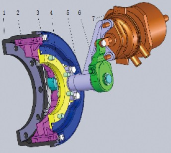
*Figure 1: Rear Wheel Brake Structure*
1. Brake drum
2. Brake shoe and roller
3. Camshaft
4. Brake bottom plate
5. Camshaft support
6. Brake adjustment arm
7. Brake chamber
**Cause Analysis**
After disassembling and re-inspecting the brake components, it was found that all parts met the required specifications, eliminating manufacturing defects as a potential cause.
**Braking Torque Calculation**
The braking torque $ M $ generated by a single brake is calculated using the following formula:
$$
M = Q \cdot L \cdot \eta \cdot \frac{f'}{R_b} \cdot m \cdot K_1 \cdot K_2
$$
Where:
- $ Q $ = Thrust of the spring brake chamber push rod (N)
- $ L $ = Length of the brake adjustment arm (mm)
- $ \eta $ = Transmission efficiency of the cam support
- $ R_b $ = Radius of the involute cam base circle (mm)
- $ f' $ = Coefficient of friction between the cam and roller
- $ m $ = Moment arm of tangential force (mm)
- $ K_1, K_2 $ = Performance factors of the two brake shoes
- $ R $ = Radius of the brake drum (mm)
The main structural parameters used in the calculation were:
$ Q = 7500\, \text{N},\ L = 132\, \text{mm},\ \eta = 0.7,\ R_b = 13\, \text{mm},\ f' = 0.15,\ m = 13.62\, \text{mm},\ R = 190\, \text{mm},\ K_1 = 1.01,\ K_2 = 0.45 $
Using these values, the calculated braking torque was $ M = 5449.58\, \text{N·m} $, closely matching the measured value of $ 5400\, \text{N·m} $. Thus, the primary cause of the insufficient braking torque is identified as an unreasonable design, which requires improvement.